![]()
Summary
“Artifact-Free Automatic Loudness Control Requires Much More Than Just “Processing for the BS.1770 Meter.”
Orban’s value-priced OPTIMOD TV 6585 surround/stereo television loudness controller builds on Orban’s 30+ year experience in television audio processing to provide audibly transparent automatic loudness control and dialog intelligibility control for one surround program (up to 7.1) or four stereo (stereo) programs. The stereo processing can operate in dual-mono mode, so it can process four subchannels in stereo or eight subchannels in mono. Put in-line and operated correctly, the OPTIMOD TV 6585 will ensure that loudness meets the requirements of the CALM Act and EBU R-128. The OPTIMOD TV 6585 is Orban’s second-generation surround/2.0 processor offers standard AES3id and SD, HD-SDI (3G) input/output and audio routing capabilities that include support for optional Dolby-E encoding and decoding. Dual redundant power supplies help ensure maximum uptime where a relay provides hard-wire safety bypass from the SDI input to the SDI output in case of hardware failure. The OPTIMOD TV 6585 is dialnorm-aware. Loudness control is excellent when measured by the ITU BS.1770 standard (as specified in ATSC A/85:2009) or by the OPTIMOD TV 6585’s built-in CBS Loudness Meters. When properly installed and set up, the OPTIMOD TV 6585 will automatically make a station compliant with the CALM Act or EBU R128. In stereo mode, the four stereo processors can be made pre-emphasis aware, allowing the OPTIMOD TV 6585 to be purchased for immediate use with analog transmitters with the assurance that it will provide no-compromise processing for digital transmissions when the need arises. A second use for the stereo processors is processing up to four different languages in DTV program streams.
Features
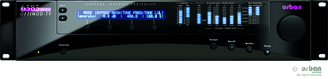
6585 front panel info
Absolute Control of Loudness and Peak Modulation
The OPTIMOD TV 6585 includes third-generation CBS Loudness Controllers for DTV applications. Separate loudness controllers are available in the multichannel and 2.0 processing chains and work with the both Two-Band and Five-Band structures. The third-generation improvements reduce annoyance more than simple loudness control alone, doing so without audible gain pumping. Attack time is fast enough to prevent audible loudness overshoots, so the control is smooth and unobtrusive. Loudness control is excellent when measured by the OPTIMOD TV 6585’s built-in ITU BS.1770 and second-generation (Jones & Torick) CBS Loudness Meters, allowing stations to comply automatically with the requirements of the CALM act. The OPTIMOD TV 6585 implements “true peak” control by oversampling the peak limiter’s sidechain at 192 kHz. This allows the OPTIMOD TV 6585 to prevent clipping in a playback device’s analog signal path by predicting and controlling the analog peak level following the playback device’s reconstruction filter to an accuracy of better than 0.5 dB. For typical program material, accuracy is 0.2 dB.
Without true peak control, analog clipping can occur even if all peak values of the digital samples are below 0 dBFS. This phenomenon has also been termed “0 dBFS+.”
Thanks to true peak control, sample rate conversion, unless it removes high frequency program energy or introduces group delay distortion, cannot cause sample peaks to increase more than 0.5 dB. For example, sample rate conversion from 48 kHz to 44.1 kHz is highly unlikely to cause sample peak clipping in the 44.1 kHz audio data.
Since 1980, Orban has sold thousands of Optimod-TV processors and these have processed millions of hours of on-air programming. No other manufacturer can make this claim. Over the decades, we have constantly refined and polished our loudness control algorithms to provide audibly transparent loudness control that never annoys audiences. Instead of using BS.1770 as a simplistic internal model that determines how loudness is controlled, we use a much more sophisticated multiband psychoacoustic model to do this. This model is based on years of research at CBS Laboratories and CBS Technology Center and was further refined by us over a 30-year period. This model allows the 6585 to control both short-term and long-term loudness. The only purpose of the OPTIMOD TV 6585’s built-in BS.1770 meter is to verify that our model controls long-term loudness effectively according to the BS.1770 standard. Thousands of hours of subjective listening tests have verified that our model controls loudness without irritating audiences. The OPTIMOD TV 6585 meters the processing; it doesn’t process for the meter. In our experience, the CBS Loudness Controller and Loudness Meter lock onto the program’s “anchor element” (typically speech) much more accurately than the BS.1770 meter, which also tends to over-indicate the loudness of material with low peak-to-RMS ratio (such as promos and commercials with a lot of “artistic compression) by 3 dB or more. The CBS technology is particularly effective in locking onto the anchor element even in the presence of effects and underscoring. Nevertheless, to accommodate organizations that will disqualify an automatic loudness controller if it causes a BS.1770 meter to read higher than a specified threshold, the OPTIMOD TV 6585 offers a defeatable “BS.1770 safety limiter” that follows the CBS Loudness Controller in the signal path. This limiter can be set to effectively limit the indications of a BS.1770-2 gated meter with 10-second or longer integration time to a preset threshold. Because gain reduction in the BS.1770 safety limiter is usually triggered by subjective inaccuracies in the BS.1770-2 algorithm itself (particularly its over-indication of “artistically compressed” material), we prefer the sound of the processing with this limiter defeated so that all loudness control is performed by the CBS algorithm.
Orban’s Optimix® Upmixer
The built-in, Orban-developed Optimix stereo to 5.0 surround upmixer provides uncolored automatic stereo-to-surround upmixing, plus phase correction that ensures that the center channel is al ways crisp and intelligible. Optimix stereo 5.0 surround upmixer is 5.1-compatible. Unlike technology derived from consumer matrix decoders, there is no program-dependent directional pumping of sound sources. Unique to this technology is extremely robust center channel phase/skew correction that never causes negative side effects. It is invaluable for older material that was originally recorded on analog tape. Optimix’s output downmixes to stereo flawlessly, and the skew correction often makes the downmix sound better than the original stereo!
There are large, important subjective differences between Optimod and competing processors. Optimod has a unique architecture that processes the center channel to correct spectral and loudness balance problems that compromise dialog intelligibility in ill-considered mixes. We have heard reports from broadcasters who have suffered increased viewer complaints about unintelligible dialog after installing the leading competitive processor. The OPTIMOD TV 6585 is exactly the opposite—in addition to flawless loudness control, it also improves dialog intelligibility and maintains a full, natural sound without exaggerated “esses, ” hollowed-out midrange, obtrusive pumping of ambient sound, and directional image shifts. Thanks to the Optimix upmixer, which cleanly extracts dialog from stereo sources, the OPTIMOD TV 6585 can even improve dialog from these sources! These factors are why the OPTIMOD TV 6585’s subjective audio quality wins every serious shoot-out when compared to its competition. For the surround processing, the OPTIMOD TV 6585 provides a simultaneous stereo downmix that is loudness-controlled, peak-controlled, and pre-emphasis aware, so it can drive an analog TV transmitter in countries that simulcast digital and analog signals.
Adaptability through Multiple Audio Processing Structures
The OPTIMOD TV 6585 features two processing structures: Five-Band for a spectrally consistent sound and Two-Band for a more transparent sound that preserves the frequency balance of the original program material. A special Two-Band preset creates a no-compromise “Protect” function that is functionally similar to the “Protect” structures in earlier Orban digital processors.
The Five-Band and the Two-Band structures can be switched via a mute-free crossfade. Audio processing can be smoothly activated and defeated on-air, allowing programs that can benefit from full dynamic range to pass through the OPTIMOD TV 6585 without dynamics compression.
The OPTIMOD TV 6585’s processing structures are all phase-linear to maximize audible transparency. OPTIMOD TV 6585’s equalizers and crossovers use 48-bit arithmetic to ensure mastering quality noise and distortion performance.
There are two distinct kinds of presets in OPTIMOD TV 6585: processing presets, which contain the settings of the 8685’s audio processing controls (like compression thresholds), and setups, which contain technical setup settings (like input reference settings and channel routing). You can modify presets and setups and save them as “user presets” and “user setups.” More then 20 factory presets can be categorized into 4 groups. Digital TV, Analog TV, Digital radio and “Pass through”.
Flexible Configuration
The OPTIMOD TV 6585 features 3G HD-SDI and AES3id input/output, plus comprehensive handling of metadata. Dolby-E encoding/decoding and Dolby AC3 encoding are optional. The HD-SDI I/O section supports SD-SDI (per SMPTE 259M); 1.5 Gbit/s HD-SDI (per SMPTE 292M; up to 720p and 1080i) and 3.0 Gbit/s single-wire HD-SDI (per SMPTE 424M; 1080p). The SDI I/O can de-embed up to 16 channels of audio, send them to the OPTIMOD TV 6585’s DSP for audio processing, and then re-embed them with video that has been delayed to maintain AV-sync. The HD-SDI module can accommodate Dolby-E® decoding and encoding via optional plug-in modules. A relay provides hard-wire safety bypass from the SDI input to the SDI output in case of hardware failure.
The OPTIMOD TV 6585 is Dialnorm-aware and can re-author metadata as needed. Seamless switching between processing and pass-through modes (where both audio and metadata are passed through without further processing) allows the OPTIMOD TV 6585 to pass pre-qualified material without modification— you can use the 6585’s transparent-sounding loudness control only when needed. This makes it easy to comply with the requirements of network program providers who preprocess their audio feeds to comply with Recommendations A/85 and R-128. In addition to standard HD-SDI I/O and AES3id I/O, the OPTIMOD TV 6585 optionally supports Dolby-E streams from and to the AES3id and SDI I/O via plug-in Dolby-manufactured modules. The OPTIMOD TV 6585 can accept and emit Dolby-E metadata via RS485 serial (per SMPTE RDD 6-2008), Dolby-E-encoded streams (when the Dolby-E decoder option is fitted), and SDI [per SMPTE 2020-2-2008 (Method-A) and SMPTE 2020-3-2008 (Method-B)].
OPTIMOD 6585’s inputs and outputs are highly configurable via remote controllable internal routing switchers. Additionally, the outputs of the multichannel and 2.0 processing chains can be independently configured to emit the output of the AGC or the output of the multiband compressor/limiter, all configurable to use or bypass look-ahead true peak limiting.
Via the internal output routing switcher, a given output signal can be applied to more than one hardware output. This allows using the OPTIMOD TV 6585 as an AES splitter.
A stereo analog monitor output appears on XLR connectors on the rear panel. It can be configured to emit any OPTIMOD TV 6585 output signal, including a downmix of the multichannel audio. The analog outputs are transformerless, balanced, and floating (with 50Ω impedance) to ensure highest transparency and accurate pulse response. They can be used to drive a transmitter, although their normal function is monitoring. An audio sync input is configurable to accept AES11id or wordclock sync. You can synchronize the output sample rate of all AES3id outputs to this input. You can also synchronize the outputs to the AES3 digital input #1 or to the OPTIMOD TV 6585’s internal clock. The sync source of each AES3 output is independently selectable. A BNC connector can accept video sync per SMPTE 274M and SMPTE 296M, which can be used as a reference for the output audio sample rate and to correctly align Dolby-E frames with video per Dolby’s requirements. The signal applied to the SDI input can also be used as a sync reference. The OPTIMOD TV 6585 contains a versatile real-time clock, which allows automation of various events (including recalling presets) at pre-programmed times. To ensure accuracy, the clock can be synchronized to an Internet timeserver.
Silence alarm and digital audio fault tally outputs are available. A Bypass Test Mode can be invoked locally, by remote control (from either the OPTIMOD TV 6585’s GPI port or the 6585 PC Remote application), or by automation to permit broadcast system test and alignment or “proof of performance” tests. The OPTIMOD TV 6585 contains a built-in line-up tone generator, facilitating quick and accurate level setting in any system. Dual redundant power supplies with independent AC line inputs help ensure maximum uptime.
Controllable
An LCD and full-time LED meters make setup, adjustment and programming of the OPTIMOD TV 6585 easy — you can always see the metering while you’re adjusting the processor. Navigation is by dedicated buttons, soft buttons (whose functions are context-sensitive), and a large rotary knob. The LEDs show all metering functions of the processing structure (Two-Band or Five-Band) in use.
An API provides remote administration over TCP/IP via the RS232 serial or Ethernet ports. The OPTIMOD TV 6585 hosts a TCP/IP terminal server to allow external control of the OPTIMOD TV 6585 from either a Telnet/SSH client or a custom third party application. All commands are simple text strings. You can recall presets, operate the input and output routing switchers and more. Password security is provided. By running Orban-supplied downloadable upgrade software on a PC. The upgrade can occur remotely through the OPTIMOD TV 6585’s Ethernet port or serial port (connected to an external modem), or locally (by connecting a Windows® computer to the 6585’s serial port through the supplied null modem cable).
Technical Specification
Technical Specification
It is impossible to characterize the listening quality of even the simplest limiter or compressor based on specifications, because such specifications cannot adequately describe the crucial dynamic processes that occur under program conditions. Therefore, the only way to evaluate the sound of an audio processor meaningfully is by subjective listening tests.
Certain specifications are presented here to assure the engineer that they are reasonable, to help plan the installation, and make certain comparisons with other processing equipment.
Performance
Frequency Response (Bypass Mode): ±0.10 dB, 20 Hz–20 kHz for 44.1 kHz or higher input/output sample rates. At 32 kHz input and/or output sample rate, the passband is reduced to approximately 14.7 kHz.
Noise: Output noise floor will depend upon how much gain the processor is set for (Limit Drive, AGC Drive, Two-Band Drive, and/or Multiband Drive), gating level, equalization, noise reduction, etc. The dynamic range of the A/D Converter, which has a specified overload-to–noise ratio of 110 dB, primarily governs it. The dynamic range of the digital signal processing is 144 dB.
Polarity (Bypass Mode; Operate Mode when processing chain is configured for linear phase): Absolute polarity maintained. Positive-going signal on input will result in positive-going signal on output.
Internal Processing Sample Rate: 48 kHz. We believe this provides maximum audible transparency by minimizing numerical “noise” in the equalizers and filters while still preserving a pure, transparent sound. The double-precision equalizers and crossover filters used throughout the 6585 produce at least 6 dB lower noise and nonlinear distortion than they would at 96 kHz.
Processing Resolution: Internal processing has 24 bit (fixed point) or higher resolution; uses 9 Freescale (formerly Motorola) 250 MHz DSPB56724 dual-core 24-bit fixed-point DSP chips.
Delay: The minimum available input/output delay is approximately 33 ms with look-ahead limiting active and 6 ms with look-ahead limiting bypassed. This can be padded to exactly one or two frames of 24, 25, 29.97, 30, 50, 59.94, or 60 frames/second video up to a maximum delay of 60 ms. (Two frames are required for 59.94/60 fps progressively scanned video.) The HD-SDI connection provides video delay of up to 11 frames to compensate for the delay of the 8685’s loudness processing (approximately one frame), and Optimix® upmixer (approximately five frames).
The output frame boundaries are time-aligned with the sync source and can be fine-tuned by up to +10/-53 pixels compared to the sync reference via the Video Time Offset setup control.
Surround Processing Stereo Coupling: All channels of the AGC and compressors are coupled using RMS summation. Peak limiters in the multiband compressor limiter and look-ahead limiters all operate uncoupled to prevent transients in a given channel from causing audible loudness modulation in other channels. In additional, the compressors acting on the center channel can be uncoupled from the remaining channels within a user-selectable window, allowing the processing to correct the balance between dialog and remaining program elements automatically.
2.0 Processing Stereo Coupling: Stereo or dual-mono. In dual-mono mode, both processing channels have the same subjective adjustments (as determined by the active preset) but are otherwise independent, making this mode appropriate for dual-language transmissions. In stereo mode, the user can set the maximum permitted gain difference between the channels in each band of the multiband compressor/limiter. 2.0 Stereo/Dual-Mono operating mode can be set via GPI, Ethernet and serial connections, internal clock-based automation, and AES3 Status Bits.
Loudness Level Meter (x4): One meter for the surround processing or four meters for the four 2.0 processing channels, all meters realized in software. For a given processing chain, two meters operate simultaneously: a long-term loudness meter displays loudness over an ungated 3-second integration time or 10-second integration time using the ITU-R BS.1770-2 algorithm (per ATSC A/85 and EBU R 128) and a short-term loudness meter uses the Jones & Torick algorithm developed at CBS Technology Center in 1981. The Jones & Torick meter’s display time constants are matched to the psychoacoustic loudness integration time of the human ear, reaching steady-state level in approximately 200 ms and having a decay time constant of approximately 300 ms. Hence, this meter can indicate the momentary loudness of transient events like pistol shots, which may be annoying to viewers but which the BS.1770-2 meter ignores because of its longer integration time. (B. L. Jones & E. L. Torick: “A New Loudness Indicator for Use in Broadcasting,” J. SMPTE, September 1981, pp 772-777.)
One ITU BS.1770-2 meter is always displayed on the 6585’s front-panel; it indicates the Surround loudness when the 6585 is in Surround mode and it indicates the 2.0 loudness of one of the four 2.0 processing channels (user selected) when the 6585 is in 2.0 Mode. In 6585 PC Remote software, all four loudness meters are displayed simultaneously when the 6585 is in 2.0 mode.
Peak Control: As recommended in ITU-R BS.1770-3, the peak limiter is oversampled at 192 kHz, yielding a worst-case overshoot of 0.5 dB at the analog output and for all output sample rates. (To achieve this performance at 32 kHz output sample rate, it is necessary to set the 6585’s lowpass filter cutoff frequency to 15 kHz.)
Optimix™ Upmixer
Location: Built into the Optimod.
Processing Delay: 146 ms
Upmix: 2.0 to 5.0; 5.1-compatible.
Auto-detection: Defeatable auto-detection can detect stereo and surround inputs automatically and switch upmixing on when stereo material is detected.
Bass Management: Bass energy below 80 Hz is not upmixed. Any energy below 80 Hz in the left/right inputs is routed to left front/right front outputs respectively so that home receivers can perform appropriate bass management for a given setup.
Downmix Compatibility: If Delay Correction is OFF, Optimix reads the Optimod’s downmix parameters (Center and Surround downmix coefficients) from the Optimod and automatically chooses gains for the five upmixed channels that make the downmixed signals identical to Optimix’s stereo inputs, assuming a Dolby Lo/Ro downmix. Optimix takes into account the settings of its Front/Rear Balance and Center Width controls.
It is the user’s responsibility to make sure that the Optimod’s downmix level controls agree with the Center Downmix Level and Surround Downmix Level in the AC3 metadata that is being transmitted to consumers. (Per Dolby, the default value of both is -3 dB.)
When Delay Correction is ON, the stereo downmix includes the effect of the center channel delay corrector, which can make the stereo downmix crisper and more intelligible than Optimix’s stereo inputs.
User Controls:
Center Width determines whether extracted center-channel information will be routed solely to the center output, or if some amount of the center energy is blended into the Left Front and Right Front outputs. While setting this control to “0” maximizes the “discreteness” of the upmix, some operators prefer to mix a certain amount of center energy into Lf and Rf to ensure that dialog is not lost completely if the center channel is not correctly set up at the consumer’s receiver.
Front/Rear Balance controls the ratio between the Lf/Rf and Ls/Rs levels above 80 Hz, which determines the amount of envelopment in the upmix.
Delay Correction automatically corrects time skew or phase shift between the left and right input channels. It prevents comb filtering in the derived center channel. This maximizes mono compatibility and maintains the best possible crispness and intelligibility in the center channel, which usually contains dialog or vocals.
Mode sets Optimix to BYPASS, UPMIX, or AUTO modes.
Installation
HD-SDI Input/Output
SD-SDI (per SMPTE 259M), 1.5 Gbit/s HD-SDI (per SMPTE 292M; up to 720p and 1080i), and 3.0 Gbit/s single-wire HD-SDI (per SMPTE 424M; 1080p). Input and output are on BNC connectors. A bypass relay is provided.
Unless the bypass relay is directly connecting the HD-SDI input to the HD-SDI output (which is true when no AC power is applied to the 6585 and when it is booting up), the HD-SDI input is internally terminated with 75Ω.
Audio Channel Support: Supports SDI and HD-SDI audio channels 1 through 8.
Dolby E Metadata Support: Supports Dolby-E metadata received through HD-SDI and RS485 interfaces per SMPTE RDD 06-2008. The metadata in the HD-SD stream must be embedded the HD-SDI VANC data per SMPTE 2020-2-2008 (Method-A) or SMPTE 2020-3-2008 (Method-B).
Digital Audio Inputs (x4)
Configuration: Each of four hardware inputs accepts two audio channels per AES3id standard, 24 bit resolution. Internal programmable routing switcher allows any of the 10 physical input channels to be routed to the LF, RF, C, LB1, RB1, LFE, LB2, RB2, STEREO L, or STEREO R inputs of the audio processing. For the 2.0 processing, unit can detect Stereo or Two-Channel status bits appearing at Input #1 and switch the 2.0 processor between stereo and dual-mono modes. Input #4 can also be used as a sync input, accepting wordclock or AES11id sync.
User Bits: Unit can pass AES3id User Bits from Input #1 to Output #1.
Sampling Rate: 32, 44.1, 48, 88.2, or 96 kHz, automatically selected.
Connector: BNC, female, shell bypassed to chassis via 1000 pF capacitor, EMI-suppressed. 75Ω impedance, terminated.
Input Reference Level: Variable from –30 dBFS to –10 dBFS.
Filtering: RFI filtered.
Bypass Relay: When the Optimod is powered down or booting up, each AES3id input is hard-wire bypassed to the corresponding AES3id output via a relay.
Digital Audio Outputs (x3)
Configuration: AESid. Internal, remote-controllable routing switcher allows sending LF, RF, C, LB1, RB1, LFE, LB2, RB2, STEREO L, STEREO R, DOWNMIX L, and DOWNMIX R to any hardware output channel.
Sample Rate: Sample Rate: Internal free running at 32, 44.1, 48, 88.1 or 96 kHz, selected in software. Can also be synced to the AES3id Input #1, or to the sync input (which supports AES11id and wordclock) at 32, 44.1, 48, 88.1 or 96 kHz, as configured in software. (Passband is limited to approximately 14.7 kHz when using 32 kHz input and/or output sample rate.)
Word Length: Software selected for 24, 20, 18, or 16-bit resolution. First-order highpass noise-shaped dither can be optionally added, Dither level is automatically adjusted to complement the word length.
Connector: BNC, female, shell bypassed to chassis via 1000 pF capacitor, EMI-suppressed. 75Ω impedance, terminated.
Output Level (100% peak modulation): –20.0 to 0.0 dBFS software controlled.
Filtering: RFI filtered.
Audio Reference Input
Configuration: Can accept wordclock or AES11id (75Ω) sync, automatically detected.
Connector: Female BNC.
Termination: Internally terminated with 75Ω.
Analog Audio Outputs
Configuration: One pair of outputs, which can be configured in software to emit LF, RF, C, LB1, RB1, LFE, LB2, RB2, STEREO L, STEREO R, DOWNMIX L, DOWNMIX R, LF/RF, C, LB1/RB1, LB2/RB2, STEREO L/R, and DOWNMIX L/R signals.
Source Impedance: 50Ω, electronically balanced and floating.
Load Impedance: 600Ω or greater, balanced or unbalanced. Termination not required or recommended.
Output Level (100% peak modulation): Adjustable from –6 dBu to +24 dBu peak, into 600Ω or greater load, software-adjustable.
Signal-to-Noise: ≥ 100 dB unweighted (Bypass mode, 20 Hz–20 kHz bandwidth, referenced to 100% modulation).
Distortion: ≤ 0.015% THD (Bypass mode, de-emphasized) 20 Hz–20 kHz bandwidth.
Connectors: Two XLR-type, male, EMI-suppressed. Pin 1 chassis ground, Pins 2 (+) and 3 electronically balanced, floating and symmetrical.
D/A Conversion: 24 bit 128x oversampled.
Filtering: RFI filtered.
Audio Sync Input
Configuration: Can accept wordclock or AES11id (75Ω) sync, automatically selected.
Connector: Female BNC, shell grounded to chassis.
Termination: Internally terminated with 75Ω.
Video Sync Input
Video Sync input (per SMPTE 274M and SMPTE 296M) can be used as a reference for the output audio sample rate and to correctly align Dolby metadata frames with video per Dolby’s requirements (SMPTE RDD 6-2008 and Dolby Labs published specifications) in cases where HD-SDI is not in use. When HD-SDI is in use, frame sync is obtained from the HD-SDI input stream.
The video reference input is on a female BNC connector and is internally terminated with 75Ω.
Remote Computer Interface
Configuration: TCP/IP protocol via direct cable connect, modem, or Ethernet interface. Modem is not supplied.
Serial Port: 115 kbps RS–232 port DB–9 male, EMI-suppressed.
Ethernet Port: 100 Mbit/sec on RJ45 female connector.
RS-485 Serial Interface (x2)
Hardware: 115 kbps RS–485 port DB–9 male, EMI-suppressed.
Compatibility: Designed to be hardware-compatible with Dolby Digital® hardware that sends and receives Dolby Digital metadata per SMPTE RDD 06-2008.
Conveying and Re-authoring Dolby Metadata
The 6585 can, via an SMPTE RDD 06-2008-compliant RS-485 serial connection or via an HD-SDI connection, automatically convey its active surround metadata value to a downstream Dolby Digital encoder like the Dolby DP-569, which must be set up according to its operating instructions to receive and act upon this input. This reduces the possibility that operator error will cause the wrong value of surround metadata to be transmitted to consumers.
To emit an RDD 06-2008-compliant signal, the 6585 must be receiving a valid input stream that is compliant with RDD 06-2008—this is necessary to synchronize the output metadata to video frame boundaries per the Dolby specification. When a valid input stream in present, the 6585 passes this stream unchanged to its output except for the following modifications:
When using any preset other than Pass-through, the ac3_dialnorm word in the output metadata stream is reauthored so it is the same as the 6585’s active Dialnorm value. When Pass-through is active, the Dialnorm value in the input metadata is passed through to the 6585’s output.
The ac3_dynrnge word in the output stream is set to 0, indicating that the downstream AC3 encoder must reauthor the line-mode DRC metadata, following the level compression profile found in the ac3_dynrng1 word in the input metadata.
The ac3_compre word in the output stream is set to 0, indicating that the downstream AC3 encoder must reauthor the RF-mode DRC metadata, following the level compression profile found in the ac3_compr1 word in the input metadata.
Remote Control ( GPI ) Interface
Configuration: Eight (8) inputs, opto-isolated and floating.
Voltage: 6–15V AC or DC, momentary or continuous. 12 VDC provided to facilitate use with contact closure.
Connector: DB–25 male, EMI-suppressed.
Control: User-programmable for any eight of user presets, factory presets, bypass, test tone, stereo or mono modes, analog input, digital input.
Filtering: RFI filtered.
Tally Outputs
Circuit Configuration: Two NPN open-collector outputs.
Voltage: +15 volts maximum. Do not apply negative voltage. When driving a relay or other inductive load, connect a diode in reverse polarity across the relay coil to protect the driver transistors from reverse voltage caused by inductive kickback.
Current: 30 mA maximum
Indications: Tally outputs can be programmed to indicate a number of different operational and fault conditions.
Power
Voltage: 100–264 VAC, automatically selected, 50–60 Hz, 75 VA.
Connector: IEC, EMI-suppressed. Detachable 3-wire power cord supplied.
Configuration: Two independent power supplies with independent IEC input connectors. Power supply health is monitored and the good supply is automatically connected to the load should one supply fail.
Safety Standards: ETL listed to UL standards, CE marked.
Environmental
Operating Temperature: 32°to 122°F / 0°to 50°C for all operating voltage ranges.
Humidity: 0–95% RH, non-condensing.
Dimensions (W x H x D): 19” x 3.75” x 15.5” / 48.3 cm x 8.9 cm x 39.4 cm. Two rack units high.
Humidity: 0–95% RH, non-condensing.
RFI / EMI: Tested according to Cenelec procedures. FCC Part 15 Class A device.
Shipping Weight: 40 lbs. / 18.1 kg
Warranty
Two Years, Parts and Service: Subject to the limitations set forth in Orban’s Standard Warranty Agreement.
Because engineering improvements are ongoing, specifications are subject to change without notice.