Summary
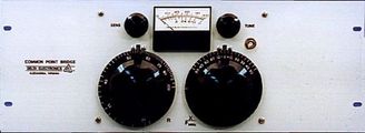
Many directional antennas have common point impedances which vary from time to time due to seasonal drift of the antenna parameters. On many occasions, remeasurement of the common point impedance indicates that the station had been transmitting with less than full power for some time because of these changes. The Common Point Bridge permits the station operator to determine the common point impedance at all times, even during normal operating hours. By minor adjustment of the common point resistance control, the station can maintain radiated power at the full license value at all times. Changes in the antenna system which affect the common point impedance are easily detected with the Common Point Bridge. This alerts the station to equipment faults and prevents citations for antenna misadjustment. The CPB-1, CPB-1A and CPB-1B thus satisfy a critical test equipment requirement of consulting and broadcast station engineers. Application Bulletin 2, available on request, describes the operation and additional uses of the Common Point Bridge.
Features
Each Common Point Bridge may be supplied with a Delta TCA RF Ammeter System factory installed. The complete series of 5, 10, 20, 40, 80 and 160 Ampere single scale and dual scale RF Ammeters with appropriate sampling transformer are available. With the RF Ammeter mounted on the bridge panel, the total RF power is easily determined from the load current and measured resistance. Consult the factory with your requirements.
The Common Point Bridges are available mounted on a standard 7″ high by 19″ wide equipment rack mounting panel. They are also available with a custom front panel with special dimensions, finish paint and legend to mount in the phasor cabinet. Consult the factory with your requirements for mounting.
Technical Specification
Technical Specification
Frequency Range:
500 kHz to 1.65 MHz
Power Rating:
at 100% amplitude modulation continuous
CPB-1: 5 kW
CPB-1A: 50 kW
CPB-1B: 100 kW
Resistance Range:
30 to 100 ohms
Reactance Range:
±50 ohms at 1 MHz
Accuracy:
Resistance:
±2% ±1 ohm
Reactance:
±2% ±1 ohm
(Provision is made for your consultant to adjust the calibration to agree exactly with your licensed resistance value)
RF Source:
Transmitter operating at normal or reduced power acts as source, no generator is required.
Detector:
Tuned internal detector with 25 µA panel meter. BNC output connector for use with external detector.
Terminals:
CPB-1:
No. 10-32 Screw Terminals
CPB-1A:
1/2″ Copper Straps
CPB-1B:
1/2″ Diameter Rod with 1/4-20 Mounting Holes
Mounting:
Standard 7″ high x 19″ wide equipment rack panel.
Optional 8-3/4″ high or 10-1/2″ high rack panel when supplied with integral TCA RF Ammeter System.
Optionally available with custom size and finish front panel for mounting in the phasor cabinet. Also available without panel for mounting directly on the phasor panel (drill template supplied).
Dimensions:
Bridge with standard front panel:
7″ high x 19″ wide x 10″ deep.
CPB-1 or CPB-1A with TCA RF Ammeter System:
8-3/4″ high x 19″ wide x 10″ deep
CPB-1B with TCA RF Ammeter:
10-1/2″ high x 19″ wide x 11-1/4″ deep
Bridge without front panel:
7″ high x 9″ wide x 9-1/4″ deep


