![]()
Summary
Summary
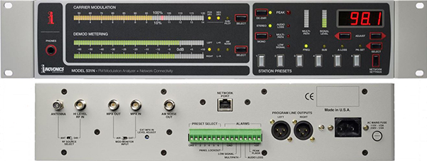
Incorporating all the necessary features for station setup, regulatory compliance, and remote monitoring, Inovonics’ 531N is the ultimate choice for essential FM signal monitoring. Dependable, direct input and off-air reception lets you keep a sharp eye on your total RF signal performance whether you’re right at the transmitter site or half way around the world.
The 531N adds new monitoring and control features which are accessible remotely via the Web interface.
The high-resolution LED bargraph displays are easy to read, and a “floating dot” program peak marker eliminates any ambiguity in the total-mod measurement. Off-air readings are qualified by Inovonics’ exclusive multipath indicator, which also aids in antenna alignment during initial station build-outs. In addition, readouts of signal strength and synchronous AM noise qualify the incoming signal and validate measurements.
Rear-panel alarms constantly check for Audio Loss, RF Loss, Multipath and Overmodulation, while advanced notifications alert personnel with e-mail or SMS messaging when any or all of the alarms occur.
Features
Features
- Complete set of metering and measurement tools to ensure FM broadcast regulatory compliance worldwide.
- Separate inputs for Antenna, High Level ?direct’ RF, and composite signal measurements.
- Full-time display of Signal Strength and Multipath effects, plus Synchronous AM noise output (BNC) to validate readings and aid in antenna alignment.
- Composite and Balanced analog Left and Right line outputs.
- Front panel metering for subcarrier injection levels: 38kHz, 57kHz (RDS), 67kHz, & 92kHz.
- Advanced Metering includes an FFT Spectrum Analyzer for the MPX, Left/Right XY plots and audio levels over time.
- Alarms for Peak Overmodulation, Signal Loss, Program Audio Loss and Multipath.
- Rear-panel closures to ground enable remote alarm indications and preset station switching.
- “Responsive” Remote Control Web interface with live audio streaming.
- SNMP control and support.
Technical Specification
Technical Specification
Off-Air Receiver Section
Type: Double-conversion superhet circuit with proprietary ultra-linear, noise-rejecting pulse-counting FM detector.
Tuning Range: 76MHz to 108.1MHz in 100kHz increments.
Station Presets: 6 user-programmable pushbutton presets; local or remote selection.
RF Inputs:
1) F connector for 75-ohm antenna.
2) BNC connector for high-level 50-ohm RF sample; 1V – 7V r.m.s.
Receiver Sensitivity: 10µV (10dBf) for 50dB mono quieting; 250µV (60dBf) required for valid Total Modulation reading.
Receiver Selectivity: ±0.25dB, 20Hz – 50kHz; –1.5dB or less at 100kHz (see Figure 1); –35dB (typ) at 200kHz (see Figure 2).
Baseband Output: BNC composite/MPX demod output; 3Vp-p at 100%-modulation.
RSSI (Incoming Signal Level): Independent front-panel LED bargraph metering of the relative strength of the incoming carrier.
Multipath Distortion Measurement: Independent front-panel LED bargraph metering of the relative degree of multipath reception-distortion effects.
AM Noise Measurement: Front-panel metering may be switched to show the relative level of the incidental, synchronous AM noise component of the FM carrier. AM noise is routed to a separate BNC output and also monitored by headphones when selected.
FM Baseband Measurements
Baseband Input: Adjustable BNC composite/MPX input to stereo decoder and subcarrier measurement circuitry. Accepts 100%- modulation levels of typical 3V p-p equating to ±75kHz carrier deviation.
Composite/MPX Metering: 58-segment LED bargraph display has quasi-peak response with ?oating peakhold. Switchable between positive deviation, negative deviation and highest of either.
Meter Resolution: 1% accuracy between 80% and 100% carrier modulation; 2% resolution between 46% and 80%. (100% = ±75kHz carrier deviation.)
Metering Integration: User-selectable at 0.1ms, 0.2ms, 0.5ms and 1.0ms.
Meter Frequency Response: +0/–1%, 10Hz – 100kHz.
Peak Flasher: Programmable in 1% increments between 95% and 120% of total carrier modulation.
STEREO DEMOD PERFORMANCE
Switch-Selected Composite/MPX Input:
1) Direct connection to the demodulated output of the off-air receiver section.
2) BNC connector accepts an external baseband input 3V p-p (adjustable) equivalent to full (±75kHz) carrier deviation.
Program Audio Outputs:
1) Balanced XLR Left & Right channel stereo program outputs deliver +4dBm at 100% monaural modulation (±75kHz carrier deviation).
2) Front-panel headphone jack.
Demod Metering Display: Dual LED bargraph displays show Left and Right or L+R and L–R demodulated program audio. The display is peak responding between +10dB and –30dB, and average responding between –30dB and – 64dB.
Stereo Audio Frequency Response: ±0.5dB, 10Hz – 15kHz.
Stereo Signal-to-Noise Ratio: Unmodulated (stereo) carrier noise is better than 65dB below 100% modulation with deemphasis applied.
Distortion: <0.075%THD at 400Hz 100% Modulation Mono. No De-Emphasis, unweighted
Stereo Separation: >55dB, 50Hz – 15kHz with an external composite/MPX input. In the off-air mode, receiver selectivity limits separation to >45dB, 50Hz – 15kHz (see Figure 3).
Stereo Crosstalk: By the M/S or S/M (stereo-difference) method, >60dB, 50Hz – 5kHz, derated to >45dB at 15kHz with external composite/ MPX input. In the off-air mode receiver selectivity limits crosstalk to >50dB, 50Hz – 5kHz, derated to >35dB at 15kHz. (See Figure 4.)
Stereo/Mono Switching: Mode switching is automatic with a front panel indicator; monaural reception may be forced with front-panel button or from the remote web interface.
Program De-Emphasis: May be turned on and off from front panel or web interface (indicator provided); internal jumper selects 50µs or 75µs characteristic.
FM Subcarrier Measurements
Meter Scaling and Resolution/Accuracy: 58-segment LED bargraph display measures stereo pilot and subcarrier levels between 2.6% and 14% with 0.2% resolution and accuracy. Injection percentages refer to 100% = ±75kHz carrier deviation.
Metering Characteristic: Peak-responding in all modes.
Measurement Filters:
1) 19kHz Stereo Pilot Tone
2) 38kHz Residual Stereo Subcarrier
3) 57kHz RDS/RBDS Data Subcarrier
4) 67kHz SCA Audio Subcarrier
5) 92kHz SCA Audio Subcarrier
Programmable Alarms
Peak Flasher: Ground-closure output gives remote indication coincidental with the front-panel Peak Flasher.
Program Audio Loss: Front-panel LED and ground-closure (remote) alarm. Programmable from the front panel to indicate when either stereo channel remains 10dB or more below 0dB for a period that may be set between 10 seconds and 2 minutes.
Low Signal: Front-panel LED and remote ground-closure alarm; fixed at a level of incoming RF signal below which modulation measurements are not valid.
Multipath: Front-panel LED and remote ground-closure alarm; fixed at a degree of multipath distortion above which modulation measurements are not valid.
Network Port
Rear Panel Connector: An RJ45 jack accepts TCP/IP Network Connections for remote setup and operation.
Settings: DHCP or Static IP address can be set from the front panel.
SNMP: Supports SNMP remote monitoring and control (MIB file can be downloaded directly from the 531N).
SMTP: Supports email services with or without SSL.
Dynamic DNS: Supports dyndns.org, no-ip.org and dnsomatic.com.
Miscellaneous
Power Requirements: 105–130VAC or 210–260VAC, 50/60Hz; 20 watts.
Size and Weight: 3½”H x 19”W x 12”D (2U); 14 lbs. (shipping).
Environmental: 0°C – 50°C operating temperature range; 95% non-condensing relative humidity; up to 3000 meters AMSL.